Product Details:
Payment & Shipping Terms:
|
Rated Input Voltage (Vdc): | -48 | Rated Input Current (A): | 33.3 |
---|---|---|---|
Input DC Voltage Allowable Range: | Working Voltage -40v ~ -58.8v Boot Voltage -42v ~ -57v | Allowable Bypass Voltage (Vac): | 120±20% |
Bypass Conversion Time (ms): | ≤4ms | Rated Capacity (VA): | 5000 |
Rated Output Power (W): | 4000 | Rated Output Voltage And Frequency: | 120Vac,60Hz |
Highlight: | 5KVA telecom inverter power supply,DC48V inverter for power systems,120V 60Hz communication inverter |
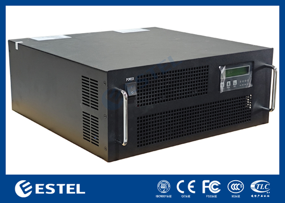
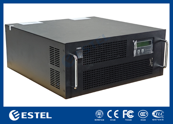
Inverter power supply
1.Inverter Power Specifications
QST048120/050C-J4A | ||
DC input | Rated input voltage (Vdc) | -48 |
Rated input current (A) | 95 | |
Input DC voltage allowable range |
Working voltage -40v ~ -58.8v Boot voltage -42v ~ -57v |
|
AC bypass input | Allowable bypass voltage (Vac) | 120±20% |
Rated input current (A) | 33.3 | |
Bypass conversion time (ms) | ≤4ms | |
AC output | Rated capacity (VA) | 5000 |
Rated output power (W) | 4000 | |
Rated output voltage and frequency | 120Vac,60Hz | |
Rated output current (A) | 33.3 | |
Output voltage accuracy (A) | 120±3% | |
Output frequency accuracy (Hz) | 60±0.1% | |
Waveform distortion rate (THD) | ≤3% (linear load) | |
Dynamic Response | 10% (load 25% ←→100%) | |
Power factor (PF) | 0.8 | |
Overload capability | ≥100%~125%, 10 minutes; 125%~150%, 15 seconds; 150%, immediately turn off | |
Inverter efficiency | ≥85% (80% resistive load) | |
Inverter conversion time (ms) |
≤4ms | |
working environment | Insulation strength (input and output) | 1500Vac, 1 minute |
Noise (1 meter) | ≤65dB | |
Ambient temperature | -5℃~+40℃ | |
humidity | 0~90%, no condensation | |
Use altitude (m) | ≤1000 | |
Mechanical Dimensions | Standard rack | 19inch 4U Rack Mount |
Weight (Kg) | 15 | |
Protective function | Input undervoltage, input overvoltage protection; output overload protection, output short circuit protection |
3.Appearance Dimensions
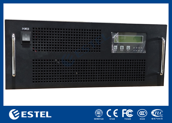
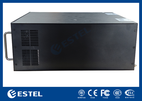
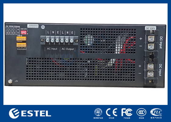
DC48V 5KVA Rear View
19inch 4U Rack Mount Front & Rear View
Port name | Function Description | Remarks | |
DC input + | Battery input + | DC module input is positive | |
DC input - | Battery input - | DC module input negative | |
AC output l | AC output L | Output line | |
AC output n | AC output N | Output zero line | |
AC input
|
L | AC input L | Input line |
N | AC input N | Input zero line | |
E | Ground | Ground wire | |
Dry contact |
Mains failure | Two points are connected when the fault occurs | |
DC fault | Two points are connected when the fault occurs | ||
Inverter fault | Two points are connected when the fault occurs | ||
Communication Interface |
A | RS485A | |
B | RS485B | ||
G | GND | ||
DIP switch |
Mode selection: No. 1 number, "1" AC main unit; "0" is DC supply. The bo-b3(2-5) address ranges from 00 to 15, the lowest is 0, and the highest is 15. You can set 15 addresses. |
After operating the dial switch To restart the power supply to take effect DIP switch to the number side is 1, to no side is 0 (0000-1111) |
Contact Person: Ms. Fiona Liang
Tel: +8613752765943 / 86-0755 23592644