|
Product Details:
Payment & Shipping Terms:
|
| System Nominal Capacity: | 215kWh | Rated Charging/discharging Power: | 100kW |
|---|---|---|---|
| Grid Power Voltage Range: | AC400V±10% | DC Voltage Range: | 672-864V |
| Operation Mode: | On-grid Operation | System Efficiency: | ≥85% |
| System Cycle Life: | ≥6000 Times | IP Grade: | IP54 |
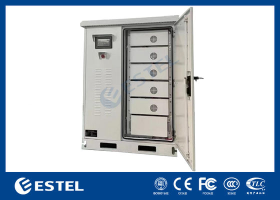
Outdoor 100kW/215kWh Integrated Energy Storage System for Grid Power Mains Electricity Saving and Solar Panel PV Photovoltaic Energy
1. System Introduction
The 100kW/215kWh air-cooled integrated energy storage system is an energy storage system composed of 280Ah lithium iron phosphate batteries. It has a wide range of applications on grid power, and it realizes peak shaving and valley filling,electricity demand management, emergency power supply, etc.
2. Advantages
1) By adopting an integrated design and single-cluster management, the circulation problem between batteries and the barrel effect are solved, which greatly enhances the safety of the system and the discharge capacity throughout the product's life cycle;
2) Highly integrated, it simplifies the design while further reducing the system cost;
3) It can achieve a diversified fire protection system: The standard configuration includes a composite gas detector and temperature-controlled aerosol;
4) Self-developed control and operation system: A set of software systems independently developed based on operational requirements.
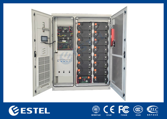
3. System structure
![]()
| 1 | Air inlet | 2 | PV input switch | 3 | Mains input switch |
| 4 | AC output switch | 5 | High-voltage box | 6 | PACK |
| 7 | Door lock | 8 | EMS | 9 | Indicator light |
| 10 | MPPT | 11 | PCS | 12 | STS |
| 13 | Fire sensor | 14 | Aerosol fire extinguisher | 15 | audible and visual alarm |
4. System Equipment List
| RYZ100215AF Integrated Energy Storage System | ||||
| No. | Equipment | Specification | Unit | Qty. |
| 1 | Cabinet | 1800*2300*1200mm, IP54 | Set | 1 |
| 2 | Battery cluster | 1P240S, 768V, 280Ah | Pc | 1 |
| 3 | BMS | 2-Layer architecture | Set | 1 |
| 4 | Fire protection system | Temperature-controlled aerosol | Set | 1 |
| 5 | PCS | 100kW | Set | 1 |
| 6 | EMS | Optional | Set | 1 |
5. Technical Parameters
| No. | Item | Parameter |
| 1 | System nominal capacity | 215kWh |
| 2 | Battery cluster grouping mode | 1P15S |
| 3 | Rated charging/discharging power | 100kW |
| 4 | DC voltage range | 672-864V |
| 5 | Grid power voltage range | AC400V±10% |
| 6 | Inverter wiring method | 3-Phase 3-Wire on-grid operation |
| 7 | Operation mode | On-grid operation |
| 8 | System efficiency | ≥85% |
| 9 | Power factor | -1~1 (adjustbale) |
| 10 | Rated charging/discharging current | 0.5P |
| 11 | Storage temperature | -30℃~60℃ |
| 12 | Allowable working temperature |
Discharging -20~55℃; Charging: 0~55℃ |
| 13 | Optimum working temperature | 25±2℃ |
| 14 | System cycle life | ≥6000 times |
| 15 | IP grade | IP54 |
| 16 | Cabinet dimension | About W*H*D=1800*2300*1200(mm) |
| 17 | Weight | About 2850kg |
| 18 | Communication | Ethernet, 4G |
| 19 | IP grade | IP54 |
| 20 | Anti-corrosion class | ≥C3 |
| 21 | System design life | ≥10 years |
| 22 | Electrical interface | 3-Phase 4-Wire +PE |
6. Detailed Introduction
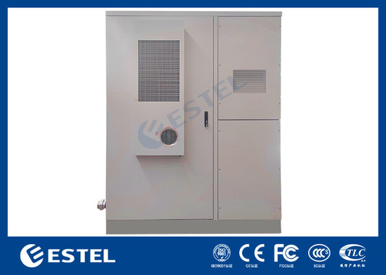
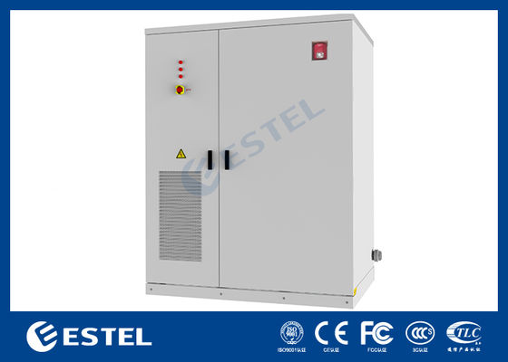
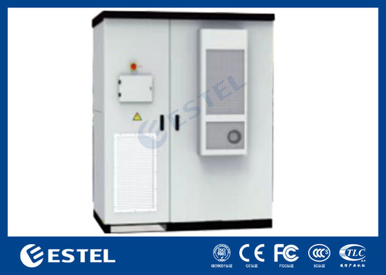
1) General
It is a standardized energy storage system, with a rated capacity of 215kWh per cabinet. It includes battery box, high-voltage box, energy storage inverter, STS, temperature control system, fire protection system, power distribution unit, BMS (Battery Management System) and energy management system EMS, and supports APP function.
The product is suitable for outdoor installation, has strong environmental adaptability, flexible installation, supports multiple cabinets, and is convenient for expansion; it is mainly used for peak shaving and valley filling on the industrial and commercial side, relieves grid pressure, and saves electricity expenses.
The product is operated in grid-connected mode. The PCS adopts a three-phase three-phase system. It is necessary to connect the N phase from the grid side to the N row in the cabinet to provide AC220V auxiliary power supply for the cabinet. The electrical schematic diagram is as follows:
2) Electrical schematic diagram
![]()
3) Battery Pack Box
The RYZ100215AF series products adopt 3.2V/280Ah LFP cells, and each Battery Pack Box contains 16 cells, grouping in the mode of 1P16S.
![]()
4) Battery cells
The system is equipped with brand-new LFP lithium batteries (3.2V/280Ah), featuring high specific energy, long cycle life, low cost, safety and no pollution. They have been widely applied in energy storage systems.
| No. | Item | Parameter |
| 1 | Battery cell type | LFP |
| 2 | Rated voltage | 3.20V |
| 3 | Rated capacity | 280Ah |
| 4 | Rated energy | 896Wh |
| 6 | Standard charge and discharge rate | 0.5P |
| 7 | Max. charge and discharge rate | 1P |
| 8 | Charge/discharge cut-off voltage | 2.5V to 3.65V |
| 9 | Number of cycles | >6000 times |
| 10 | Battery cell calendar life | >15 years |
| 11 | Battery attenuation rate | The attenuation is less than 6% every three years |
| 12 | Charge and discharge efficiency | ≥94% |
| 18 | Weight | 5.49kg |
| 19 | Dimension (L*W*H) | 174.7x71.7x204.4mm |
5) Battery Cluster
A battery cluster is a unit composed of multiple battery packs connected in a certain electrical way, including battery racks, energy storage batteries, power and sampling circuits, electrical interfaces and other components. A single cabinet consists of 15 1P16S battery packs and a 100kW energy storage inverter to form a lithium iron phosphate air-cooled energy storage integrated cabinet with charging and discharging functions. The nominal capacity of the cabinet is 215kWh.
| No. | Description | Parameter |
| 1 | Battery cluster energy (kWh) | 215.04 |
| 2 | Grouping mode | 1P15S |
| 3 | Nominal voltage (V) | 768 |
| 4 | Operating voltage range (V) |
672V-864V |
| 5 | Rated charge and discharge rate | 0.5P |
| 6 | Rated charging and discharging current | 140A |
![]()
6) Power Conversion System (PCS)
The Power Conversion System (PCS) controls the charging and discharging process of the energy storage battery system, performs AC/DC conversion, and directly supplies power to AC loads when there is no grid power. PCS consists of a DC/AC bidirectional converter, a control unit, etc. The PCS controller receives background control instructions through communication, and controls the converter to charge or discharge the battery according to the sign and size of the power instruction, thereby adjusting the active power and reactive power of the power grid. The PCS controller communicates with the BMS through the RS-485 interface to obtain battery pack status information, which can realize protective charging and discharging of the battery and ensure safe battery operation.
![]()
7) Battery Management System (BMS)
The BMS adopts a 2-layer architecture. Each battery management system consists of a Battery Management Unit (BMU) and a Battery Control Unit (BCU). The BMS system has functions such as high-precision detection and reporting of analog signals, fault alarm, upload and storage, battery protection, parameter setting, passive balancing, battery pack SOC calibration, operation account authority and password management, and information interaction with other devices.
8) Battery Management Unit (BMU)
The slave control unit BMU realizes real-time monitoring of the battery status by accurately collecting the voltage and temperature of each single battery. The module has a reliable data communication function, and can communicate with the battery management system master control unit or other necessary equipment during system operation.
9) Battery Control Unit (BCU)
The main control unit BCU is the core of the control of battery management system. It detects the voltage and temperature of the battery cells by communicating with the slave control units, and detects the external characteristic parameters such as the total voltage of the battery pack, the charge and discharge current, and the insulation resistance to ground. It estimates and monitors the internal state of the lithium battery (capacity, SOC, SOH, etc.) according to appropriate algorithms. On this basis, it realizes the charge and discharge management, thermal management, insulation detection, single cell balancing management and fault alarm of the lithium battery pack; it can exchange data with PCS, EMS, human-machine interface and other devices through the communication bus, and communicate with BMU through daisy chain.
| No. | Item | Parameter |
| 1 | Device Model | BCU |
| 2 | Current Detection | 0A~±300A (Optional) |
| 3 | Voltage Sampling Accuracy | 1% (Rated) |
| 4 | Communication Interface | RS485,CAN |
| 5 | Power supply Voltage | 12VDC (Rated) |
| 6 | Device Power Consumption | ≤3W |
| 7 | Operating Temperature | -40℃~+65℃ |
| 8 | Environmental Humidity | ≤95% |
| 9 | Altitude | ≤4000m |
| 10 | Maximum BMU Management Quantity | 64 PCS |
| 11 | SOC Calculation Error | ≤5% |
Contact Person: Ms. Fiona Liang
Tel: +8613752765943 / 86-0755 23592644
| Factory Address:BUILDING 3, NO.213, YUEHAI AVENUE, XIEGANG TOWN, DONGGUAN CITY, GUANGDONG PROVINCE | |
| Sales office:3A-8, SHUIWAN 1979 SQUARE (PHASE II), NO. III, TAIZI ROAD, SHUIWAN COMMUNITY, ZHAOSHANG STREET, NANSHAN DISTRICT, SHENZHEN | |
| +00-86-13752765943 | |
| info@estel.com.cn | |