Product Details:
Payment & Shipping Terms:
|
Input Frequency: | 45Hz~66Hz (Rated 50Hz/60Hz) | Nominal Capacity: | 3000W (176VAC~290VAC) |
---|---|---|---|
Ac Input Voltage: | 85Vac To 290Vac | Communicate Ports: | CAN Bus (CANH/CANL) |
Output Currency: | 42V DC~58V DC (Rated 53.5V DC) |
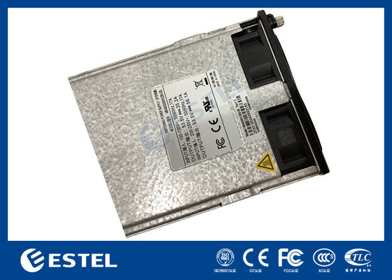
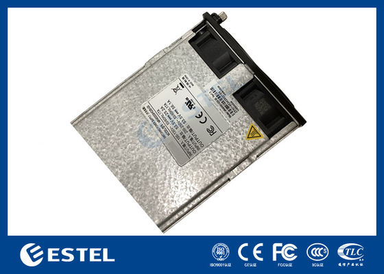
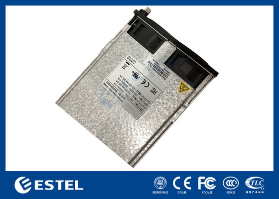
MR483000HG2B-GS Rectifier Module
1. Product Introduction
MR483000HG2B-GS is a power supply device that converts standard AC voltage into stable 48Vdc for
communication power supply system.
For a larger load capacity, the rectifier modules can be connected in parallel, or an additional independent monitoring module can be used for intelligent control.
The rectifier module is a plug-in modular unit designed to be compatible with racks and cabinets.
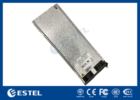
1.1 Appearance
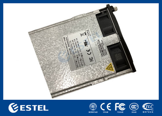
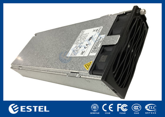
Figure 1-1 Appearance
1.2 Operating environment
Item | Configuration |
Operating temperature |
–10℃~+75℃ Note: When the ambient temperature is -10℃~ 55℃, it works normally; At 55℃~ 65 ℃, the output power is linearly derated to 80% ;At 65℃~75℃, the output power is linearly derated to 40%,. And when the power system is at -40℃, it can start normally after the input is powere on. Output voltage waveform is not required. |
Storage temperature | –40℃~+75℃ |
Relative humidity | 5%~95%(no condensation) |
Altitude |
≤4000m(When the altitude ranges from 3000 m to 4000 m, the operating temperature decreases by 1ºC for each additional 200 m) |
1.3 Electrical Characteristics
Item | Input parameters |
Operating Voltage | 85Vac to 290Vac |
Frequency |
45Hz~66Hz; Rated value is 50Hz/60Hz |
Input current | ≤18A |
Power factor | ≥0.99(220Vac@20%~100% load) |
THD | ≤5%(50%~100% load) |
Item | Output parameters |
Output voltage |
42V DC~58V DC Rated value is 53.5V DC |
Linear power derating |
3000W( 176V AC~290V AC) 3000W~1250W( 175V AC~85V AC) |
Regulated voltage precision | ≤±0.6%Vo |
Ripple and noise | ≤200mVp-p( bandwidth≤20MHz) |
Standby power | ≤4W |
Startup duration | 3s~8s( Instant start mode) |
Output hold-up time |
>10ms |
Phone noise weighting voltage |
≤2mV |
Wide-band noise voltage |
≤50mV(3.4kHz~150kHz) ≤20mV(0.15MHz~30MHz) |
1.4 Mechanical characteristics
Item | Specification |
Dimensions |
41.5mm( H)×106.4mm(W)×291mm( D) Note: For slot design, please contact sales for 3D model of the module |
Weight(Without packaging) |
<2Kg |
Cooling mode | Forced air cooling, built-in fan (with linear speed regulation function) |
Figure 1-2 Product drawing
1.5 Output characteristics
176Vac≤Input voltage≤290Vac&-10°C≤Ambient temperature≤45°C
Output current(A)
Figure 1-3 Output characteristic curve
-10°C≤Ambient temperature≤45°C
Input voltage(VAC)
Figure 1-4 Input Voltage Derating Curve
176Vac≤Input voltage≤290Vac
Figure 1-5 Temperature Derating Curve
Figure 1-6 Efficiency curve
1.6 Other features
Item | Index |
Protection Features | |
Input over voltage protection |
|
Input over-voltage recovery | Input voltage<290Vac ,automatic recovery |
Input under-voltage protection | Input voltage<80±5Vac output off |
Input under-voltage recovery | Input voltage>80~90VAC, automatic recovery |
Output over-voltage protection |
|
|
|
![]() |
|
Output current limiting protection |
See module output characteristic curve |
Output short-circuit protection | It can be short-circuited for a long time, and it can be automatically restored after the short-circuit disappears. |
Overtemperature protection |
With over temperature protection |
Safety/EMC/Surge Protection | |
Certification & Safety |
|
EMC |
|
Lightning protection | 5KA 8/20μs |
1. Module introduction
Reliability | |
MTBF | >500,000 hours (25℃) |
Audible Noise | |
Specification | ≤55dB(A) (40℃) |
1.7 Interface description
Table 1 Definition of module gold finger
Pin number | Pin function description |
1,2 | Output 48V- |
3,4 | Pre-charge |
5,6 | Output 48V+ |
7 | Group address wire of rectifier |
8 | Group inner address wire of rectifier |
13 | CANL |
14 | CANH |
31,32 | module protection ground |
33,34 | AC input neutral( N) |
35,36 | AC input phase line( L) |
1.8 Module panel introduction
Table 2 Description of the indicator lights of the rectifier module
Indicator |
Indicator color |
Status | Status description | Suggested solution |
Power indicator |
Green |
On | Module AC input is normal | Normal state, no action required |
Off |
The AC input of the module is abnormal (no input power supply, input power supply over-voltage and under-voltage, etc.) |
Check whether the input is normal; if the input is normal, replace the rectifier module |
||
4Hz flashing (4times/sec) |
Manual query status | Normal state, no action required | ||
Alarm indicator |
Yellow |
Off | No abnormal alarm | Normal state, no action required |
On |
Temperature pre-alarm (ambient temperature exceeds 65℃ ~ over-temperature shutdown) |
Check whether the ventilation of module are blocked and whether the ambient temperature is normal |
||
Dormancy shutdown (when the module is in dormancy shutdown, only the protection indicator is on, and the module does not report an alarm) |
Normal state, no action required |
|||
290Vac<Input voltage<300Vac |
Check if the input voltage is normal | |||
Module current limiting | Normal state, no action required | |||
4Hz flashing (4times/sec) |
Module hardware address error | Check if module is inserted in place and locked | ||
0.5Hz flashing (1times/2s) |
The communication between the module and the outside is interrupted |
Replace the rectifier module or monitoring module; check the CAN bus wiring of the power system for errors |
||
Fault indicator |
Red |
Off | No abnormal alarm | Normal state, no action required |
On |
The output is locked due to over-voltage or the module is not inserted in place |
Unplug the rectifier module, wait for more than 1 minute, and then insert it | ||
No output caused by internal fault of rectifier module | Replace the rectifier module |
2. Module user guide
This chapter mainly introduces the correct use methods in some applications of the rectifier module, and some precautions during application.
2.1 Module installation
2.2 Module fixation
If the design or processing tolerance of the slot of the finishing module is not well controlled, the module will not work properly, be damaged, etc. It is recommended to design according to the slot 3D model provided by Megmeet or purchase the demanded module slot from Megmeet.
2.3 CAN Bus Termination Resistor
In order to ensure the communication quality of the module, the CAN bus needs to use T-type wiring, and star-type wiring is not recommended.
It is necessary to install a 120-Ω matching resistor on the head and tail of the CAN bus. After adding the resistance, the resistance of the CAN bus is 60 Ω .
If there is a monitoring module or a host computer on the CAN bus, you need to confirm whether the monitoring module or the CAN bus of the host computer has a built-in default 120 Ω resistance, and ensure that the
impedance of the CAN bus is 60 Ω .
2.4 Hi-pot test
The module has built-in lightning protection circuit, and the input L and N have gas discharge tubes to the ground. If the withstand voltage test is performed, the grounding screw of the lightning protection circuit needs to be removed (the red circle in the figure below), otherwise it will cause the withstand voltage test to fail.
After the hi-pot test, replace the screw, otherwise the module may be damaged by lightning strikes.
2.5 Lightning protection design
The rectifier module has a built-in D-level lightning protection circuit, which can withstand the lightning current of 5KA 8/20μs waveform. If the system needs to pass a higher level lightning current, such as a C-level (20KA 8/20μs) lightning strike, the system needs to install a C-level lightning protection device, and follow the classification principle of lightning protection design, between the C-level lightning protection device and the module. There should be enough distance (recommended distance should not be less than 5M) or install lightning protection decoupler or make hollow decoupling coil. Otherwise, the rectifier module may be damaged when struck by lightning; If the system needs to meet higher-level lightning protection requirements, such as B-level lightning protection.
There needs to be a C-level lightning protection device between the B-level lightning protection and the rectifier module, and there must be sufficient distance or decoupling between the various levels of lightning protection.
2.6 Ventilation Requirements
The rectifier module is cooled by a fan, with forced ventilation from front to back. The design of the rectifier module mounting frame must ensure that the rectifier module is located in the vent and is not blocked, and the air temperature entering each rectifier module cannot exceed the specified range of the working ambient temperature.
2.7 Module replacement
The rectifier module can be uninstalled or installed while the power system is running (hot-swappable) for easy installation and maintenance.
Steps
1. To replace the module, loosen the screw on the handle of the module (turn counterclockwise a few turns to loosen the screw), pivot the handle 90 degrees to the open position.
2. Grasp the handle and pull the module firmly from the rack.
3. To replace the module, loosen the screw on the module (turn counterclockwise a few turns to loosen the screw), pivot the handle 90 degrees to the open position.
4. Put the module into the rack mounting position and with the handle in the open position, push the module into the rack.
5. Push the handle into the front panel of the module to securely lock the module to the rack, then tighten the screw on the handle.
Contact Person: Ms. Fiona Liang
Tel: +8613752765943 / 86-0755 23592644