|
Product Details:
Payment & Shipping Terms:
|
| Input Mode: | Single-phase Two-wire Input | Input Voltage: | 85Vac To 300Vac |
|---|---|---|---|
| Nominal Input: | 100Vac To 120Vac 200Vac To 240Vac | Frequency Range: | 45Hz-66Hz |
| Maximum Input Current: | ≤24A | Surge Current: | Meet The Criteria: ETSI300132-3 |
| Efficiency: | ≥96.6%@peak Value | Power Factor: | ≥0.99@220Vac 20-100% Load |
| Highlight: | Hot Swappable Communication Power Module,96 Percent Communication Power Module,4000W Communication Power Module |
||
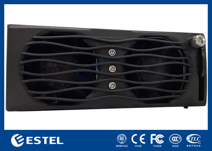
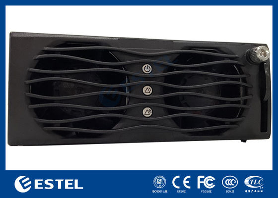
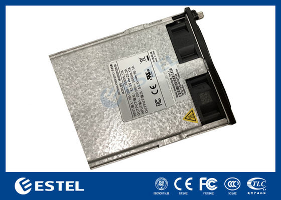
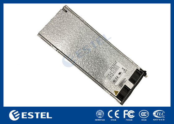
MR484000SG1 4000W 75A High Efficiency Communication Power Module 96 Percent Efficiency Wide Input 85 300VAC Hot Swappable
1. Electrical specifications
1.1 Input characteristics
| Input mode | Single-phase two-wire input |
| The input voltage | 85Vac to 300Vac |
| Rated input voltage | 110Vac / 220Vac |
| Nominal input | 100Vac to 120Vac 200Vac to 240Vac |
| Frequency range | 45Hz-66Hz |
| Maximum input current | ≤24A |
| The surge current | Meet the criteria: ETSI300132-3 |
| The efficiency of | ≥96.6%@peak value |
| The power factor | ≥0.99@220Vac 20-100% Load |
| The input current is THD |
<3% @≥50% Load <8% @≥20% Load |
| Leakage current | <3.5mA@264Vac |
| Rated power |
Rated 4000W@176ac (176Vac~300Vac excess output; 176Vac~85Vac linear derating to 1600W, specific as input power limit curve) |
| Input the insurance | L/N Wire fuse30A |
| Maximum input voltage | 320Vac(Power supply must not be damaged) |
| Power down retention time | 10ms |
Note: 1. The minimum starter voltage is less than 95VAC.
1.2 Output characteristics
1.2.1 Output voltage and current adjustment rate
| The output voltage | +53.5Vdc |
| Output voltage setting value | +53.5±0.1Vdc |
| Adjustable range of output voltage | +42Vdc~+58Vdc |
| Unbalance degree of uniform flow | ≤±3% |
| Source effect | ±0.1% |
| Effect of load | ±0.5% |
| Accuracy of steady flow | ≤±0.8A |
| Voltage regulation accuracy | ±0.6% |
| Minimum current | 0A |
| Rated current | 75A |
| Peak current | 81.3A |
| Temperature coefficient (1/℃) | ≤±0.02% |
| Standby power consumption | ≤5W |
| Maximum capacitive load | 4000uF |
| Maximum number of parallel | 31 |
Note: The output current regulation and communication interruption of the rectifier module are as follows:
1) The output current of the rectifier module can be adjusted according to the current command. The adjustment range is 1A~81.3A.
2) If the communication between the rectifier module and the monitoring module is interrupted for more than 1 minute, the output of the rectifier module will automatically return to 53.5V and the state of
unlimited flow.
1.2.2 Output ripple and noise
| Ripple and noise (peak-peak) |
| ≤200mVp-p |
Note: 1) Ripple and noise test: Ripple and noise bandwidth set at 20 MHz.
1.2.3 Output dynamic response
|
The voltage overshoot |
Jump slope | The load change | Recovery time |
|
+53.5V±5% |
0.1A/uS |
25%-50% 50%-75% |
≤200us (±0.6%) |
| +58V | 0.1A/uS | 0%-100% |
/( Does not trigger overvoltage protection ) |
Note: load jump cycle 4ms.
1.2.4 Output overshoot
| The output voltage | Overshoot voltage | |
| boot | To turn it off | |
| +53.5V | ≤1% | ≤1% |
Note: Load range during test: minimum to maximum.
1.2.5 Startup output delay time
| The output voltage | 220Vac@25℃ |
| +53.5V | 3S~8S |
Note: Start-up delay time is the time from AC power on to output voltage to 42VDC.
1.2.6 Power conversion
| Input Voltage | Output Power |
| 200Vac~290Vac | 4350W |
| 176Vac~200Vac | Linear derating |
| 176Vac | 4000W |
| 85 Vac~176Vac | Linear derating |
| 85Vac | 1600W |
![]()
The output 53.5~58V is based on the upper limit power, and the output 42~53.5V is based on the external characteristics and the proportional power limit
The above is a curve that limits the maximum output power according to the input voltage; all are
theoretical limit values, and the actual limit will have a certain deviation due to the input voltage accuracy (±2V), output voltage accuracy (±0.6%) and output current accuracy (0.8A) ; The voltage error of the power conversion point is <±2V.
1.2.7 Output characteristic
![]()
Remarks: The above are the theoretical limit values, the actual limit will have a certain deviation due to the current accuracy (current error <±0.8A) .
1.2.7 Startup output delay time
| The output voltage | 220Vac@25℃ |
| +53.5V | 3S~8S |
Note: Start-up delay time is the time from AC power on to output voltage to 42![]()
1.2.8 Over-temperature drop curve
|
The temperature |
note |
| ≤45℃ | With the output |
| 45℃~75℃ | Linear derating |
| >75℃ | Shutdown, after shutdown since the recovery of temperature return > |
Note:
The input is greater than 200Vac, the output 53.5~58V is based on the upper limit power, and the output 42~53.5V is based on the external characteristics and the ratio of the power limit;
The input is less than 200Vac, and the output 53.5~58V is limited in proportion to the input power limit; the output 42~53.5V is limited in proportion to the external characteristics and the input power limit.
The above are the theoretical limit values, and the actual limit will have a certain deviation due to ambient temperature accuracy (±2°), input voltage accuracy (±2V), output voltage accuracy (±0.6%) and output current accuracy (0.8A); The ambient temperature error of the rated point is less than ±2℃.
1.2.9 Noise voltage
| Noise voltage | The maximum | note |
| The telephone weighs the noise voltage | ≤2mV | |
| Broadband noise voltage | ≤50mV | 3.4~150KHz |
| ≤20mV | 150~30000KHz | |
| Discrete noise voltage | ≤5mV | 3.4~150KHz |
| ≤3mV | 150~200KHz | |
| ≤2mV | 200~500KHz | |
| ≤1mV | 500~30000KHz |
1.3 Protection function
1.3.1 Output short circuit protection
| output voltage | Note |
| +53.5V | Long - term short circuit, can be automatically restored after short circuit disappeared |
1.3.2 Output overvoltage protection
Over voltage protection can be divided into internal and external overvoltage protection. The internal overvoltage fault range is 58.5VDC~ 60.5VDC, which can be set by monitoring. In case of failure, the module locks. If the external voltage is greater than 63VDC and lasts more than 500ms, the module is locked. After entering the lock machine protection state, it is necessary to disconnect the AC power first, and then power on again, so that the power can work again.
1.3.3 Output undervoltage warning
The range is 37VDC~39VDC. When it is lower than the undervoltage alarm value, it will output normally and report an alarm..
1.3.4 Input overvoltage protection
| The input voltage | note |
| 310±10Vac | Output off, voltage can be recovered after normal |
| Recovery point return >10V |
Note: Input overvoltage protection shall be tested at 75A rated load.
1.3.5 Input undervoltage protection
| The input voltage | Note |
| 80±5Vac | Output off, voltage can be recovered after normal |
| 80Vac-95Vac | Output recovery, output recovery point return >;5V |
1.3.6 Over temperature protection
| Temperature | Note |
| ≤45℃ | The module can output the maximum output power without over-temperature protection, and the module operates normally |
| 45℃~75℃ | The module power is linearly derated to 2000W |
| >75℃ | Shutdown, self-recovery temperature difference after shutdown>10℃ |
1.4 Communication function between rectifier module and monitoring module
The CAN bus communication mode is adopted between the rectifier module and the monitoring module, which supports the remote software version upgrade, and the module's address CAN be set through the
address board.
After the communication between the rectifier module and the monitoring is interrupted for 1 minute, the rectifier module starts up and the output voltage and current limit values return to the default values.
The CAN interface in the rectifier module needs to be designed in isolation. The power supply of CAN is + 5VDC, which is provided inside the rectifier module.
The main monitoring information of rectifier module is as follows:
1) Voltage regulation and current regulation function: to meet the floating charging requirements of the battery and to meet the voltage regulation requirements;
2) Single module switch machine control;
3) Protection and alarm information feedback:
Utility fault: Utility fault (AC input over voltage);
Module protection: temperature warning;
Module failure: no output caused by over-voltage shutdown, fan failure, over-temperature shutdown or other internal reasons of the module;
(The module is in hibernation and shutdown state, and the mains power failure is not reported to the module fault).
1.5 LED
The power supply LED indicator is installed on the side of the power panel. The output state is shown in the table below.
| mandatory sign | Indicator light | normal | abnorma l | Abnormal reason |
| Power running indicator | color | state | state | Power failure (no AC input, AC input over voltage), module no output. |
| Warning light | green | bright | destroy | Temperature warning (the ambient temperature exceeds 65 ℃ ~ over temperature shutdown). Dormancy shutdown (the module only lights the alarm indicator light, the module does not report the alarm). Communication interruption (warning light flashing) . Input overvoltage warning, (input voltage over 290VAC ~ overvoltage protection). |
| Failure light | huang | destroy | bright | Input overvoltage, input undervoltage, output overvoltage, bus overvoltage, bus undervoltage, fan failure, environmental overtemperature, input voltage type error, environmental temperature sampling NTC abnormity, input ultra-high voltage. |
2. Insulation performance
2.1 Insulation Impedance
| input-to-output |
Test voltage 500VDC, insulation resistance ≥2M (Normal atmospheric pressure, room temperature, relative humidity < 90%, no condensation) |
| Input to the protected area | |
| Output to the protected area |
2.2 Resistant to high voltage
| input-to-output | DC voltage 4240VDC1minute ≤1mA |
|
Input to the protected area |
DC voltage 2120VDC 1minute ≤1mA |
|
Output to the protected area |
Equivalent DC voltage 710VDC 1minute ≤1mA |
Note: if the circuit has lightning protection device, the voltage test should be performed after the opening of the electrical gap tube, the input lines should be short connected (L&N) together, and all the output lines should be short connected together.
3. Safety standards
Power supply safety meets the following standards:
GB4943
IEC/EN60950 IEC/EN62368-1
Power supply safety certification:
CE certification (LVD and EMC directive requirements)
Contact Person: Ms. Fiona Liang
Tel: +8613752765943 / 86-0755 23592644
| Factory Address:BUILDING 3, NO.213, YUEHAI AVENUE, XIEGANG TOWN, DONGGUAN CITY, GUANGDONG PROVINCE | |
| Sales office:3A-8, SHUIWAN 1979 SQUARE (PHASE II), NO. III, TAIZI ROAD, SHUIWAN COMMUNITY, ZHAOSHANG STREET, NANSHAN DISTRICT, SHENZHEN | |
| +00-86-13752765943 | |
| info@estel.com.cn | |