
|
Product Details:
Payment & Shipping Terms:
|
| Operating System: | Linux | Application: | Environmental Monitoring And Control |
|---|---|---|---|
| Operating Temperature: | -40°C ~+60°C | Ingress Protection: | IP30 |
| Alarm Output: | Relay Output | Contact Power: | ≤10W |
| Alarming Water Level: | 5mm | Operating Current: | < 15 MA (Max) |
| Usage: | Industrial | Measurement Parameters: | Temperature, Humidity, Air Quality, Light Intensity, Noise Level |
| External Dimensions: | : Φ68 Mm * Φ34.8 Mm * 31.5 Mm | Product Type: | Hardware |
| Monitoring Current: | <0.7mA(12V) | Remote Monitoring: | Yes |
| Alert System: | Email And SMS Notifications | Voltage: | 150VDC(MAX) |
| Tilt Alarm Threshold: | 15°±2° | Operating Voltage: | 85 VAC To 300 VAC , Or 20 VDC To 60 VDC |
| Alarm Water Level: | (2±0.5) Mm | Input Voltage: | 12V±50% (6-18V) |
| Weight: | 2 Pounds | Digital Input: | Eight Ways |
| Alerts/Notifications: | Email, SMS | Alarm Volume: | >80dB (front 3m) |
| Relay Output: | 6-way Relay Control Output | Installation: | Wall-mounted |
| Model: | FSU1000 | ||
| Highlight: | infrared temperature sensor for industrial use,network temperature sensor with warranty,industrial monitoring infrared sensor |
||
THS-E04 temperature sensor a network-type temperature sensor that uses infrared sensor technology
1. Product Overview
The THS-E04 temperature sensor is a network-type temperature sensor that uses infrared sensor technology. The sensor features a high-precision temperature detection module, making it convenient to measure temperature and transmit data to external devices via the RS485 interface. It is ideal for temperature monitoring and data collection and is widely used in factories, warehouses, cold-chain transportation, and other locations, meeting the demand for real-time temperature monitoring.
2. Technical Parameters
Power Supply: DC 9-30V ±10%
Power Consumption: ≤0.2W
Measuring Temperature: -20~70°C
Measuring Humidity: 0-100% RH
Accuracy: Temperature ±0.3°C (full range), Humidity ±3% RH (25°C)
Communication Protocol: MODBUS-RTU protocol
Communication Distance: >1000 meters
Product Dimensions: 86×86×30 mm
Product Weight: 105g
3. Typical Applications
As shown in Figure 1: Sensor connection diagram
The sensor connects to data acquisition devices via RS485 for real-time data transmission.
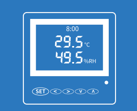
4. Appearance and Button Functions
SET Key: Press the SET key to enter the settings mode. After entering settings mode, the screen will display the parameter settings interface. In the settings interface, pressing this button toggles between the settings for baud rate and address configuration.
In the baud rate settings section, press and hold the "SET" key for more than 3 seconds to return to normal operation mode while setting the baud rate.
The baud rate range is: 1200, 2400, 4800, 9600, 14400, 19200, 38400, 57600, 115200. The address range is: A-255.
5. Baud Rate and Address Setting
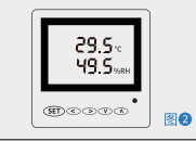
Figure 3: Baud rate settings interface
Once settings are completed, hold down the SET key for more than 3 seconds to enter the working state. The set parameters will be saved.
6. Electromagnetic Compatibility
Electrostatic Discharge Immunity: Reference standard IEC61000-4-2 (GB/T17626.2)
Power Frequency Magnetic Field Immunity: Reference standard IEC61000-4-8 (GB/T17626.8)
Surge Immunity: Reference standard IEC61000-4-5 (GB/T17626.5)
7. Terminal Wiring Diagram
J2 Terminal Wiring Description:
RS+ (Port 1): RS485 positive terminal
RS- (Port 2): RS485 negative terminal
GND (Port 3): Ground
DC+ (Port 4): 12VDC power supply input
8. Installation Instructions
The three fixed screw hole distances are 63mm, with the maximum hole diameter of 4.8mm.
When drilling holes for the panel, the distance between the two screw holes should be between 58-60mm.
During installation, ensure the sensor's front side faces outward and avoid installing it in air vents or areas with significant air movement.
Communication Protocol
1. Basic Protocol Rules
The communication protocol for the THS-E04 temperature and humidity sensor adopts the MODBUS RTU protocol, as described below:
All communication follows a master-slave model. The device is the master, and information and data exchanges are initiated by the master device (listening to the device communication protocol).
Device initialization and protocol control are managed by the communication response protocol instructions.
Devices must not initiate communication from the slave side.
All communication lines and devices can be connected via RS485. A device typically forms a simple network, supporting up to 25 devices. It can also be connected via an RS232 interface.
![]()
![]()
Contact Person: Ms. Fiona Liang
Tel: +8613752765943 / 86-0755 23592644
| Factory Address:BUILDING 3, NO.213, YUEHAI AVENUE, XIEGANG TOWN, DONGGUAN CITY, GUANGDONG PROVINCE | |
| Sales office:3A-8, SHUIWAN 1979 SQUARE (PHASE II), NO. III, TAIZI ROAD, SHUIWAN COMMUNITY, ZHAOSHANG STREET, NANSHAN DISTRICT, SHENZHEN | |
| +00-86-13752765943 | |
| info@estel.com.cn | |